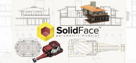
SolidFace is a 2D/3D parametric historic constructive CAD modeler. In addition to 3D modeling, it allows project creation entirely in 2D, such as mechanical parts, civilian plants, layouts, etc. Solidface is a sum of Parasolid ® Siemens 3D modeler core and 15 years of 2D/3D CAD development resulting in a product with powerful...
Všechny recenze:
1 uživatelských recenzí - Pro vygenerování hodnocení je potřeba více uživatelských recenzí
Datum vydání:
22. pro. 2014
Značky

Abyste mohli tento produkt přidat do svého seznamu přání, začít ho sledovat nebo ho zařadit mezi ignorované, musíte se nejprve přihlásit.

Čeština není podporována

Tento produkt nepodporuje Váš místní jazyk. Seznam podporovaných jazyků je k dispozici níže na této stránce.


Informace o softwaru

Part module

SolidFace Sketch automatically creates parametric reference for modeling features that can be edited in a very simple and interactive way. This is an in-house developed module and fully integrated with the 3D module.

SolidFace allows multiple bodies creation. A powerful tool helps in the development of dependent parts from a single part file.

The parameterization allows not only an easy model editing, but also parts family creation that is an important issue in automating creation of variant models with the same constructive basis, such as fasteners, automotive, hydraulic and civil components. From a parametric part you can automatically generate dozens of others parts through parameters association, such as thickness, length, number and diameter of holes, color, material, information, text, etc.

Assembly module

Easy, accurate and effective, this module enables you to build assemblies using modeled parts and sub-assemblies. The automatic link between the modules facilitates the manipulation of assembly parts, thus any editing on a part or assembly, results in an automatic change in the assembly that references this component.

You can build assemblies by inserting components created outside the assembly document; this is known as bottom-up assembling or if you need to construct a component that needs dimension references of some assembly components, you can create it, within the Assembly module. This operation is called in-context or top-down part creation.

To facilitate the assembly process, the part elements can be enabled or disabled at any time without interfering the process of inserting (bottom-up) or creating (top-down) new components.

Drawing module

Besides the 2D draft capabilities explained in the SolidFace drawing product, you can also insert parts and assemblies into the drawing module in order to generate automatic orthographic, sections and details views. These views and dimensional annotations are created according to DIN and ANSI norms. Personalized by the designer. The 3D models views can be displayed in several model styles. The sections or details views are automatically created and aligned with the base view.

Another advantage of the automatic link between the modules is the ability to copy and paste 2D geometric entities to the 3D Sketch module in order to use it as reference geometry to 3D features operations like extrude, revolve, etc.

Exploded view

An exploded view is a diagram, picture or technical drawing of an object, that shows the relationship or order of assembly of various parts. This allows the components (parts and sub-assemblies) to be visualized with defined displacements. The exploded view can be enabled or disabled at any time of the project creation.

3D Direct modeling

Interact directly with the geometry of the model. Manipulate it by pushing, pulling, or twisting.

Keeping the steps that create the final model, direct modelling allows the features geometry to be parametric modified by editing the feature used to create the new faces.

2D/3D Movement simulation

One of the many capabilities of logical conditions is to enable the system to detect the collision of components assembly. The collision or the simulation process can be aborted and analyzed at any time. This makes possible not just a simple mechanism video demonstration but also a real-time movement simulation.

The parameterization capability is one of the greatest advantages of SolidFace and it is present in all design steps. 3D Motion simulation is no different; the simulation is updated simultaneously with the movement. Another important capability is the simulation of 2D mechanisms, which can be performed either in 2D drawing or in 3D sketch module.

Product specification

  • Part module;
  • Sketch module;
  • Assembly module;
  • Drawing module;
  • Exploded view;
  • Communication with other applications through the Windows ® clipboard (Clipboard);
  • Communication with other CAD software via standard X_T®, X_B®, DWG®, DXF®, BMP, etc;
  • 3D history construction tree and direct command editing;
  • Associative dimensioning and fully adapted to a number of standards;
  • Geometric operations and editing through direct entity or feature tree selection;
  • Parametric and associative geometric construction references such as midpoint, center of arcs and circles, endpoint, etc;
  • Creation of complex geometries such as cams, gears etc;
  • 3D features construction such as Extrude, Revolve, Loft, Sweep, etc;
  • 3D family of parts creation using CSV (Excel files association) or TXT table files;
  • Configurable toolbars;
  • Possibility of managing multiple projects simultaneously (multiple instances);
  • The graphics screen can be divided up to 16 view windows, allowing the visualization of several project details;
  • Print Preview;
  • 3D and PDF® printing compatibility;
  • Local and global variables;
  • Definition of parametric variables via commands, questions, or variable tables;
  • Logical conditions If-then-else;
  • Parametric generation of bill of materials with associative link with Excel ® and Access ®;

Systémové požadavky

    Minimální:
    • OS *: Support Windows ® XP/Vista/7/8
    • Procesor: 32/64bit Processor (x86/x64);
    • Paměť: 2 GB RAM
    • Grafická karta: 256MB Off-board graphics card or higher
    • Připojení: Širokopásmové připojení k internetu
    • Pevný disk: 500 MB volného místa
    Doporučené:
    • OS *: Support Windows ® XP/Vista/7/8
    • Procesor: 32/64bit Processor (x86/x64);
    • Grafická karta: 1GB graphics card or higher
    • Připojení: Širokopásmové připojení k internetu
    • Pevný disk: 2 GB volného místa
* Od 1. ledna 2024 podporuje klient služby Steam pouze systém Windows 10 a novější.

Uživatelské recenze produktu SolidFace Parametric CAD Modeler 2D/3D

Druh verdiktu


Druh nabytí


Jazyk


Časové rozmezí
Pro zobrazení recenzí z daného časového rozmezí ho tažením vyberte v grafu výše nebo přímo klikněte na určitý sloupec.

Zobrazit graf


Odehraný čas
Recenze budou filtrovány dle odehraného času uživatelů v době jejich psaní.


Žádné minimumŽádné maximum

Zobrazení
Recenze budou zobrazeny ve vybraném pořadí.


Více informací
Zobrazit graf
 
Skrýt graf
 
Filtry
Nesouvisející recenze jsou vyloučeny
Odehraný čas:
Recenze primárně ze zařízení Steam Deck
Filtrům neodpovídají žádné další recenze
Abyste viděli všechny recenze, upravte filtry výše
Načítání recenzí...