Jun 23, 2023
Kerbal Space Program 2 - mikey

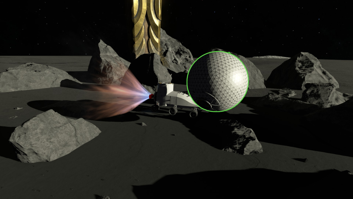
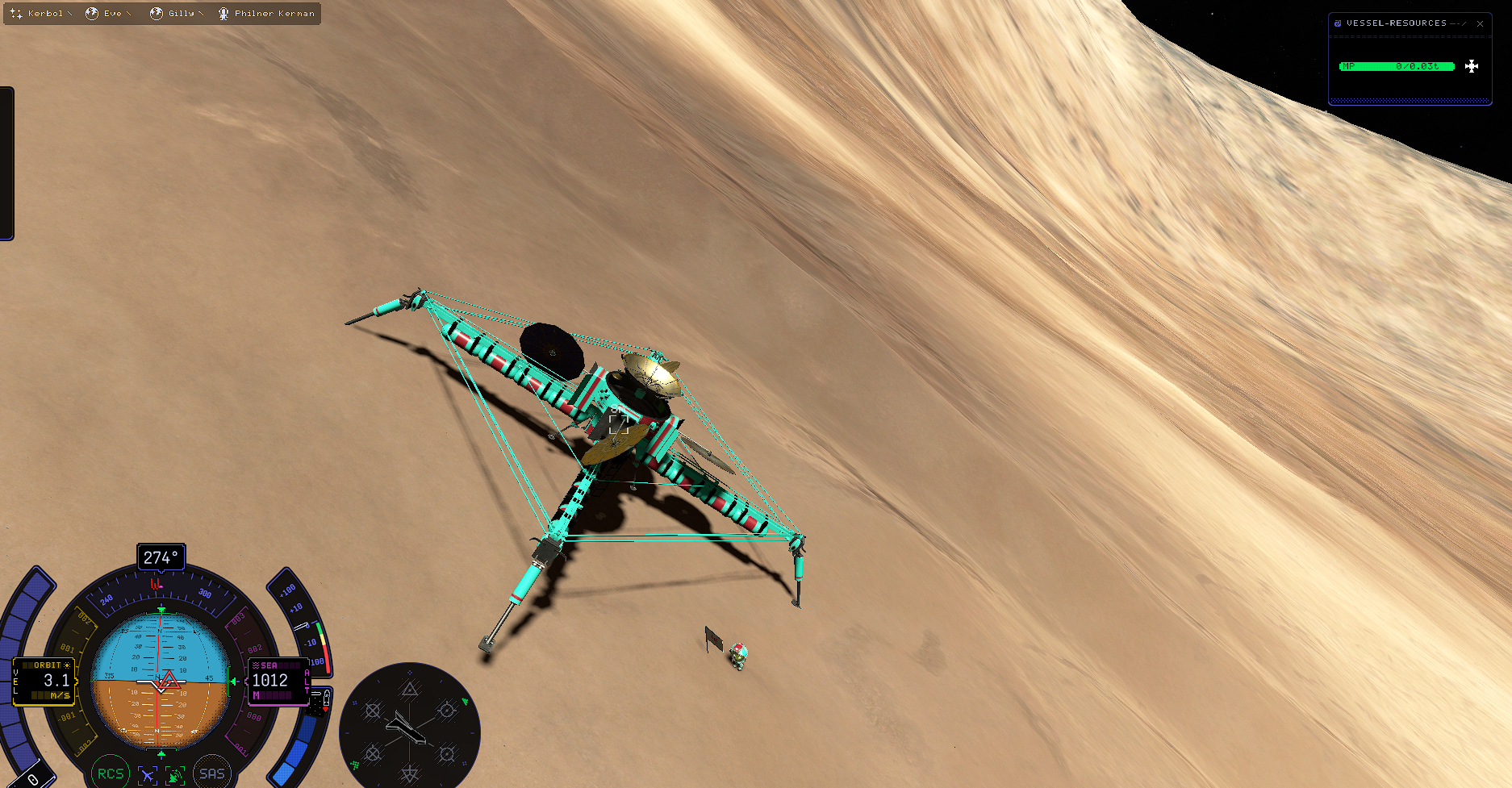
Thanks to Community Member Kavaeric for making the image!
Happy day-after-update, fellow Kerbonauts!
Many of you have had a few hours to experience the v0.1.3.0 update, and hopefully you have found the gameplay experience improved! Many players are reporting significantly better framerates, but there are more than just performance gains on the menu. Among the new fixes and features we’re most excited about for this update:
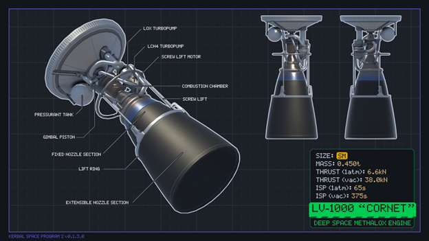
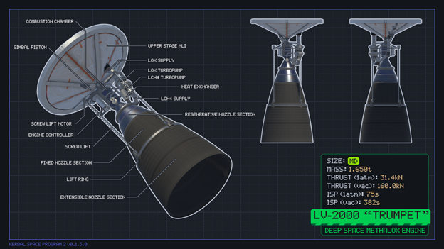
- New parts, including three new engines, new docking ports, and the A.I.R.B.R.A.K.E.
- The Flight HUD UI is now re-scalable via player settings
- Several decoupling-related flight bugs have been resolved
- We knocked out several of the vehicle-falls-through-terrain bugs
- We nailed that really annoying VAB bug that kept you from putting down procedural parts after picking them up
- We strengthened wing attachments with a new automatic multi-joint system
- We fixed the asymmetrical separation forces on radial decouplers, restoring the beauty of booster separations
What's Next
This update represents an incremental step in the ongoing Early Access process of addressing game-breaking bugs while moving toward our first Roadmap update, which will add Science collection, a new Mission system, and parts progression to the game. We still have quite a few game-breaking bugs at the moment, as well as aspects of gameplay that still need refinement (wobbly rockets, overactive control surfaces, strange SAS behavior). We will be posting our new top-ten most wanted bugs next week (three of which will be carrying over from our previous top-ten list). If you’re playing the latest update and you come across a bug that you’d like to report, please do so via the Bug Reports subforum on the KSP Forums; you can upvote existing reports, or if your issue isn't listed, you can submit a new report through the form. We will be following those threads very closely to track which issues are most important to the community as a whole.We are aware that one of the decoupling fixes in this update has introduced a new issue that breaks aerodynamic drag after a decoupling action. Thanks to early reports from the community, we have been able to reproduce the bug and are working on a fix. If the fix proves stable and low risk, we will consider releasing a hot fix in a few days.
Some players have also correctly noted that the orbital decay and SOI transit trajectory bugs are still present in v0.1.3.0 - while we had high hopes for an eleventh-hour breakthrough, neither fix made it across the finish line in time. In the days after code lock, a new fix for the SOI transit issue was submitted and is being tested. Our engineers have also isolated the orbit decay issue and believe they have a good remedy on deck. With updates, there’s always the temptation to hold the build just a couple more days to sneak in additional fixes (which we actually did this week). Alas, at some point the train has to leave the station, but it’s at least comforting to know that these issues will be addressed in an upcoming update. We appreciate your patience, and we hope that the changes that did make it into this week’s update have improved the game for you.
Other questions that we've been asked:
Where's reentry and heating?
We are working hard on both. We expect reentry VFX to arrive earlier than thermal systems and heat-related part destruction, so there may be a short phase during which reentering vehicles look like they’re being heated, but really aren’t. We don’t want to reverse any of our recent framerate gains, so we’re taking the time needed to make sure reentry is both awesome-looking and performant. To give you better visibility into the work taking place in this area, we will be posting a new dev blog about the heat system soon!
What's going to be in v0.1.4.0?
As we continue to work through our critical bugs list, those that are fixed by the next update will be included. We are still targeting foundational bugs and playability issues. As we work down through the list, we’ll report on our progress.
When is the Science Update?
The first of the headline Roadmap updates - which will add Science, Missions, and an R+D Center, is still several months away. A lot of work is going into the "Dot Two" update — deep architecture work, bug fixing, new systems, and a lot of new content. We will continue to release incremental updates until that time, with the goal of eliminating the major game-breaking bugs prior to v0.2.0.0. We’ll provide a release date for that version as soon as we can
Steam Sale
With summer upon us, Private Division is holding a 20% off sale for KSP2. This sale ends on July 13th. If you’ve got a friend who has an interest in participating in Early Access, now is a great time to hop on board!Upcoming AMA
On Thursday, June 29 at 10am PT, our Art Director Kristina Ness will be fielding your questions about KSP2, and this is a rare opportunity to get detailed answers about the game's art! You can submit questions for here on this post!Weekly Challenge
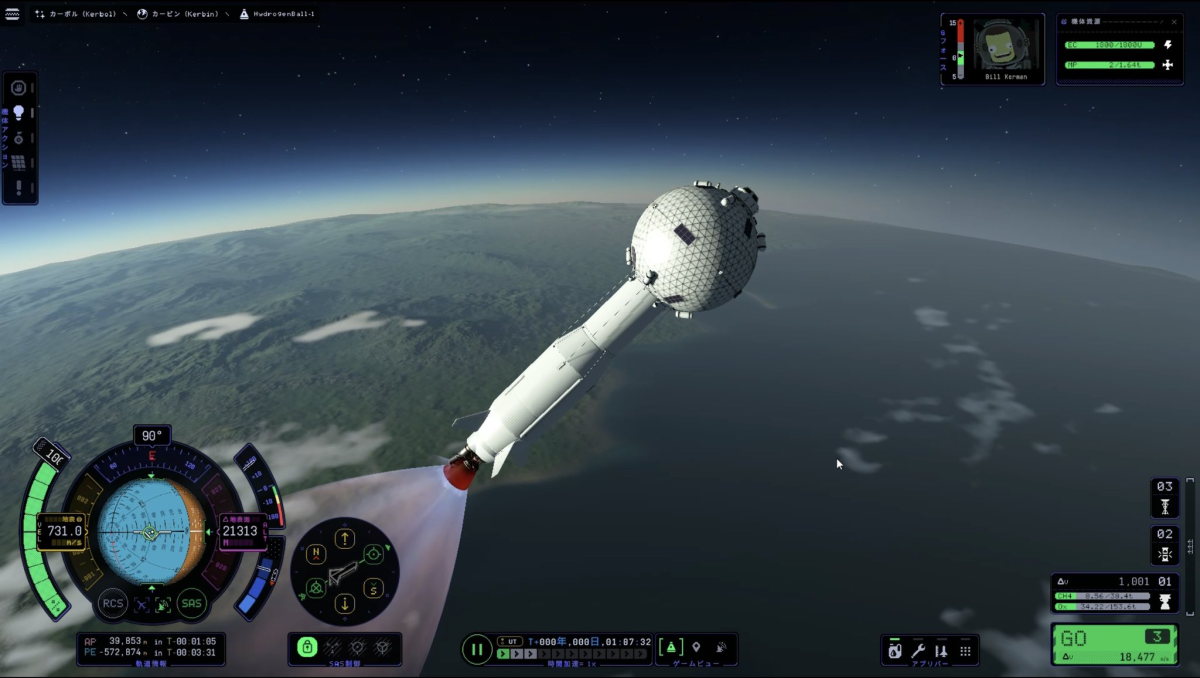
Last week's "Score a Goal" challenge was extra challenging, but those who conquered it created some very original vehicles!First, there's this submission from Miss, which deserves special mention as it’s the only attempt that involves not only a ball, but a rocket-powered foot!
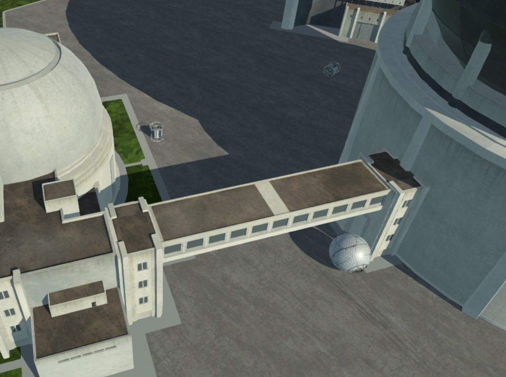
Squidplaz did some reaction wheel magic to get a ball under the R+D Center bridge:
User pyasupro posted this beauty on Twitter, and made goals on both the Mun and Moho:
This week's challenge: we're going to Jool! Here are the deets:
- 🏆 Primary Goal: Launch a single-Kerbaled mission (only 1 spacecraft may depart Kerbin's SOI, but it can be built in Kerbin orbit) that passes through the SOI of all 5 of Jool's moons at least once before returning to Kerbin.
- 🏆 Secondary Goal: Same as primary, but land a probe on each of Jool's moons (the probes don't have to return).
- 🏆 Jeb Level Goal: Same as secondary, but plant flags on Bop and Pol.
- 🏆 Val Level Goal: Plant flags on all 5 moons of Jool in one mission before returning safely to Kerbin.
Share: 


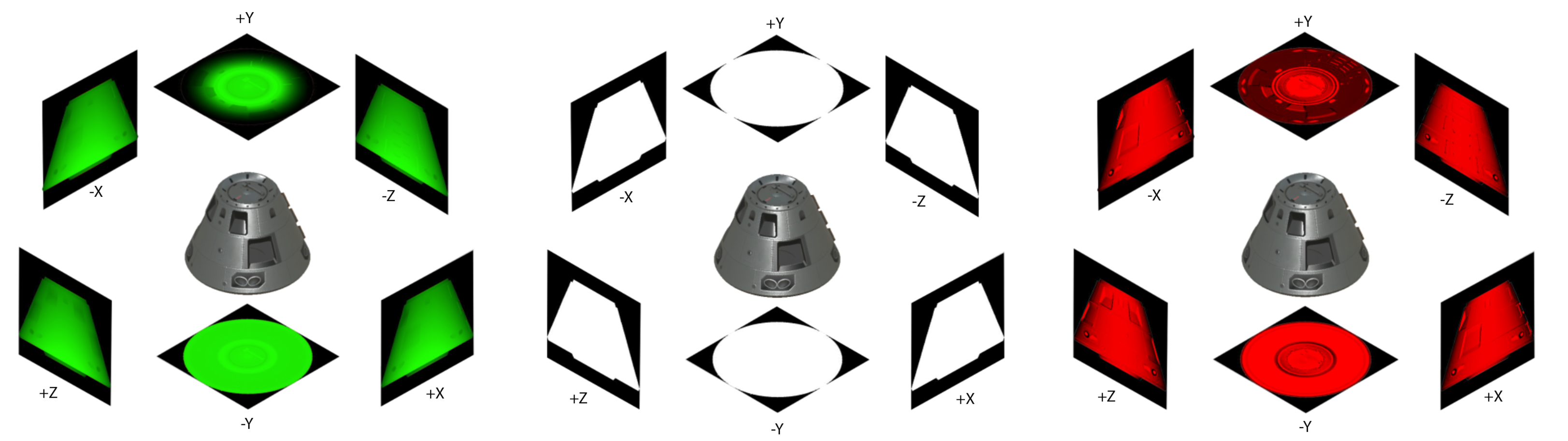
 Drag cube data for the Size M conical command pod.
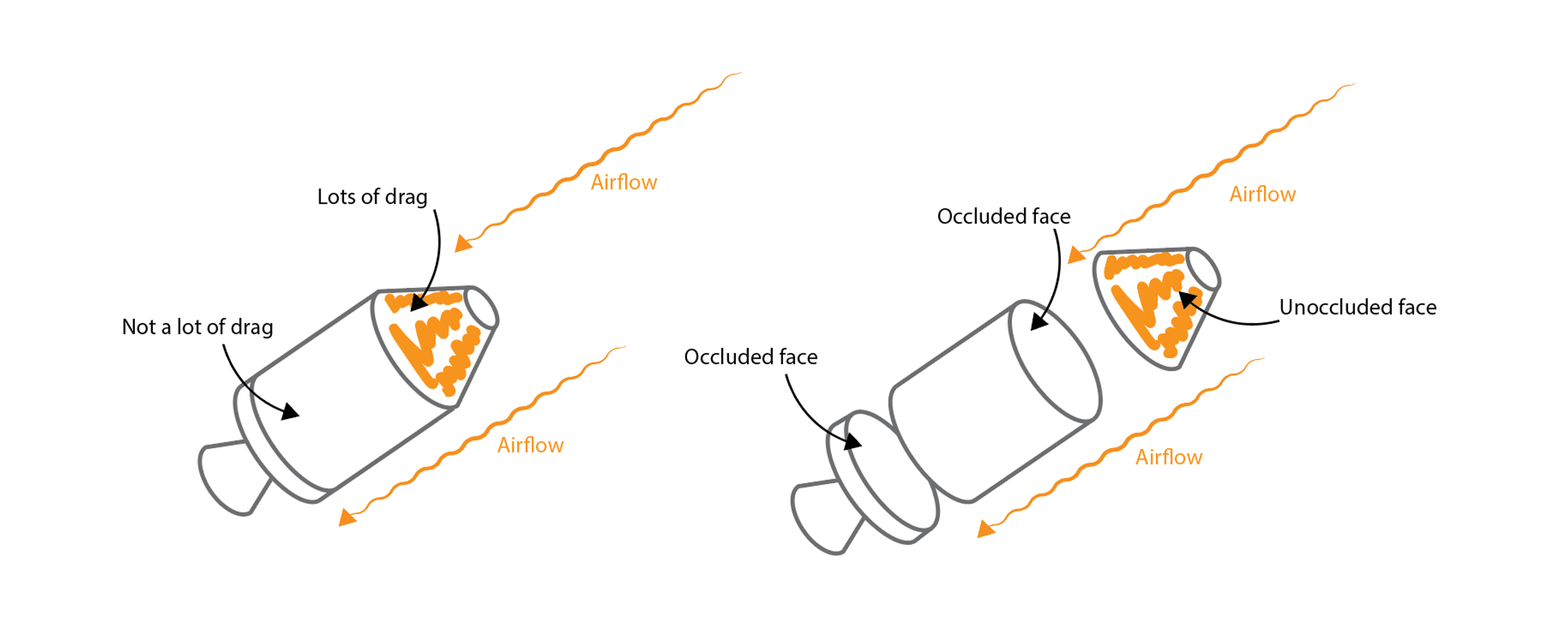 Schematic examples of how we'd expect a vessel made of 3 parts to behave with respect to the occlusion of each of its faces.
 Schematic example of subtracting drag cube Y+ and Y- faces for same-size parts, in two airflow directions.
 Schematic example of subtracting drag cube Y+ and Y- faces for different-size parts, in two airflow directions.
 How a hollow part behaves by default in the KSP2 drag model to show how it doesn't appropriately occlude the part below it.
 "Filling in" hollow parts to allow them to shield parts behind them.
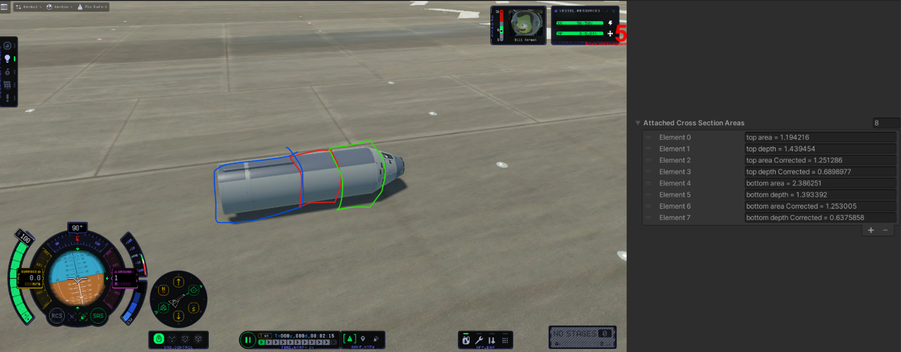 In this image you get to experience some internally famous 'Chris paint-overs', terrible MS paint scrawls trying desperately to get a point across.
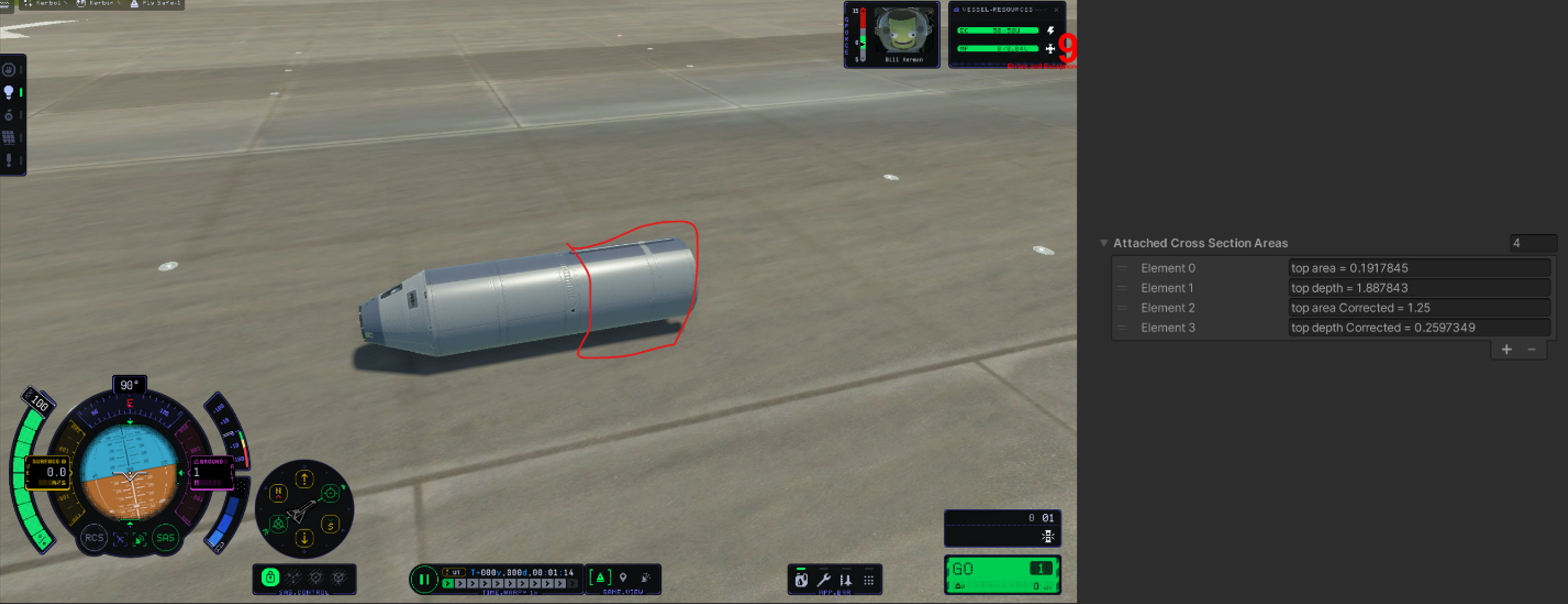 More live occlusion values.
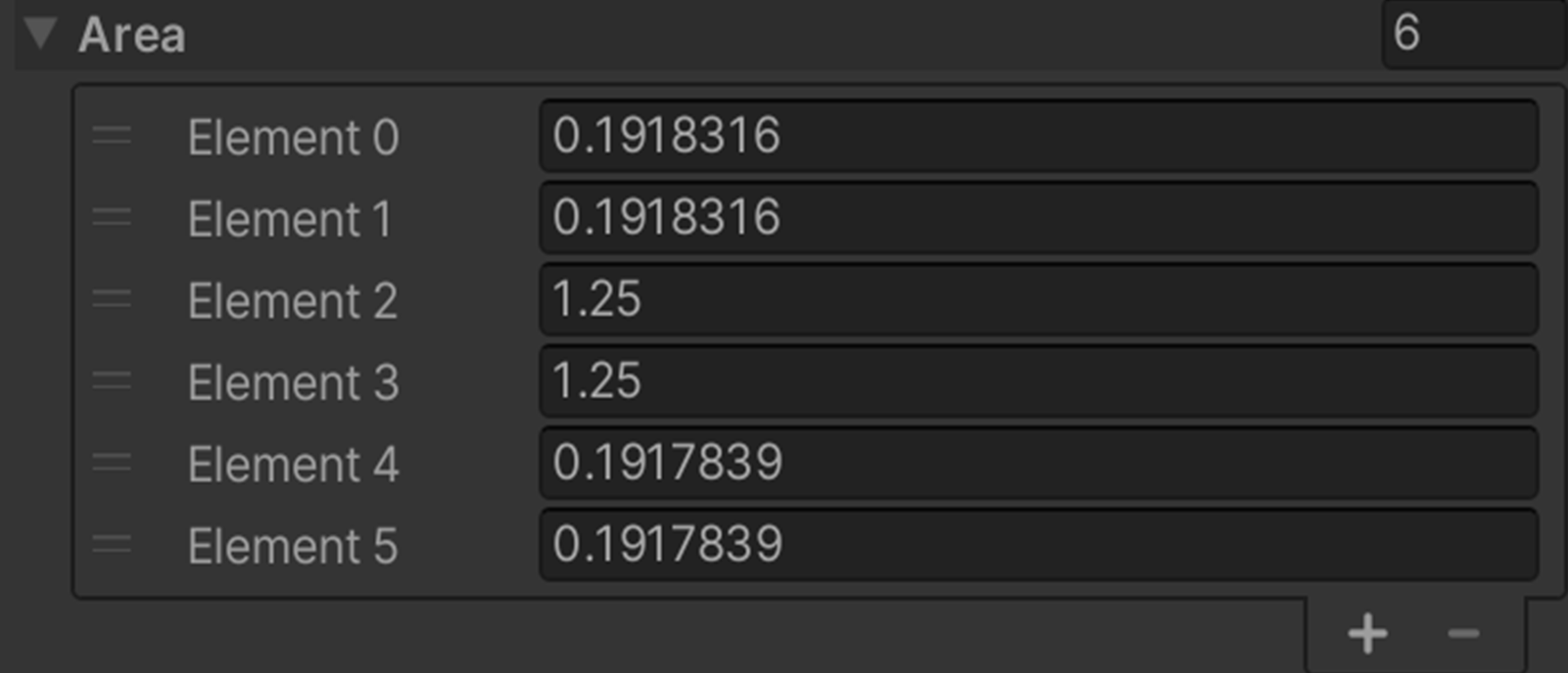 Drag Cube areas for the Size S decoupler.
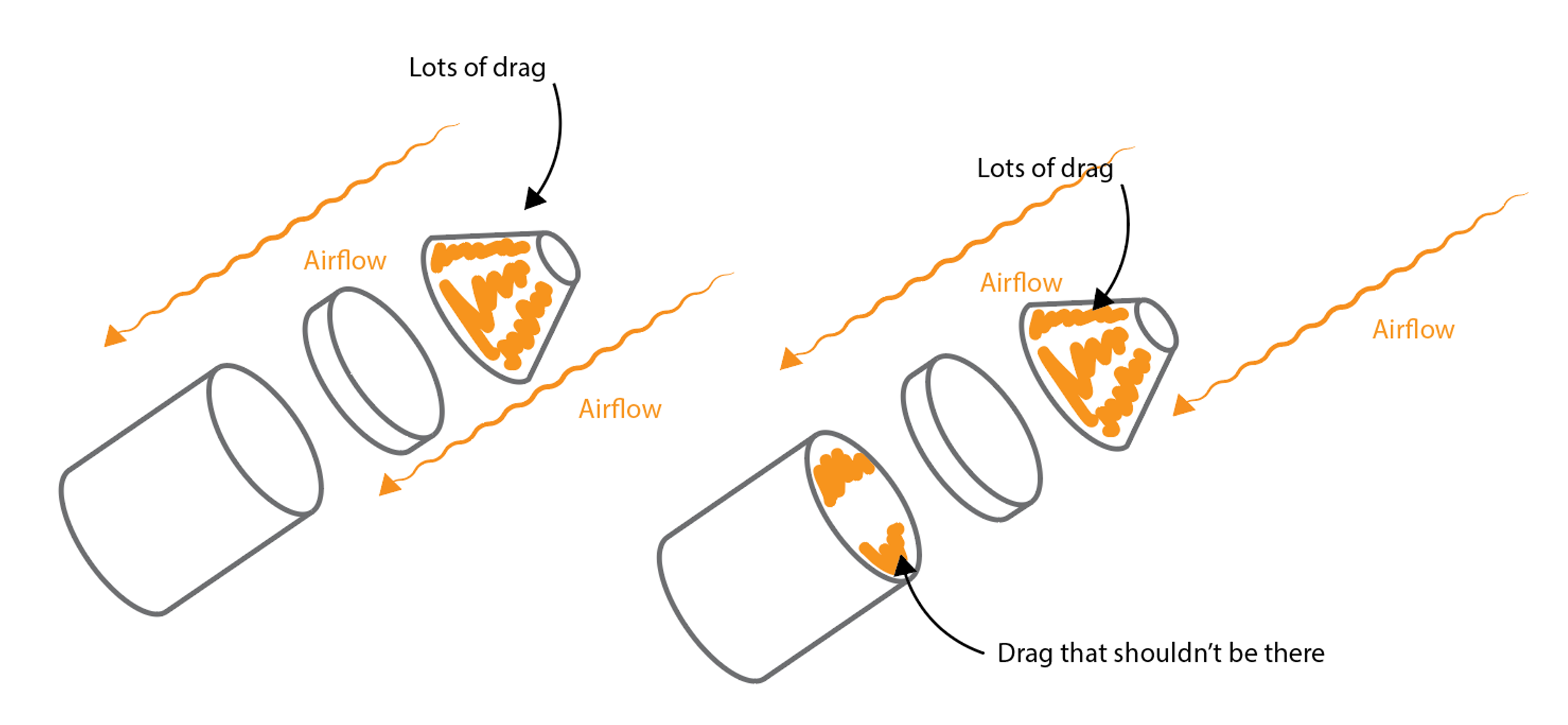 What we'd expect for post-occlusion drag (left) versus what we were getting (right).
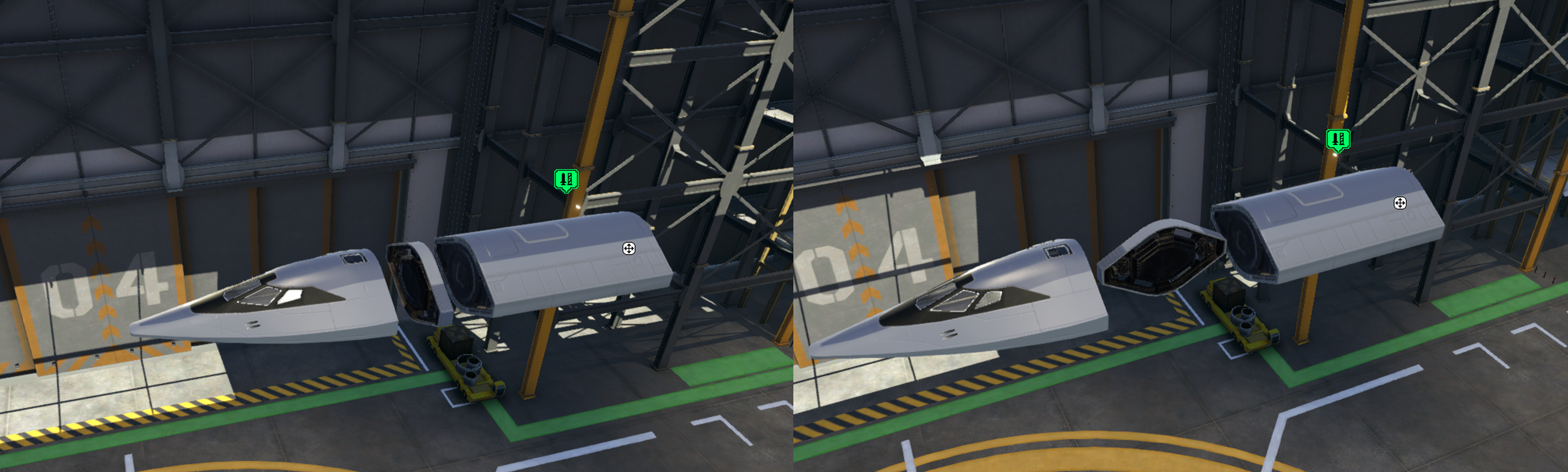 A silly example of what we'd see (left) versus what the occlusion model would see (right). In this case you get too much drag, because there's not enough occlusion.
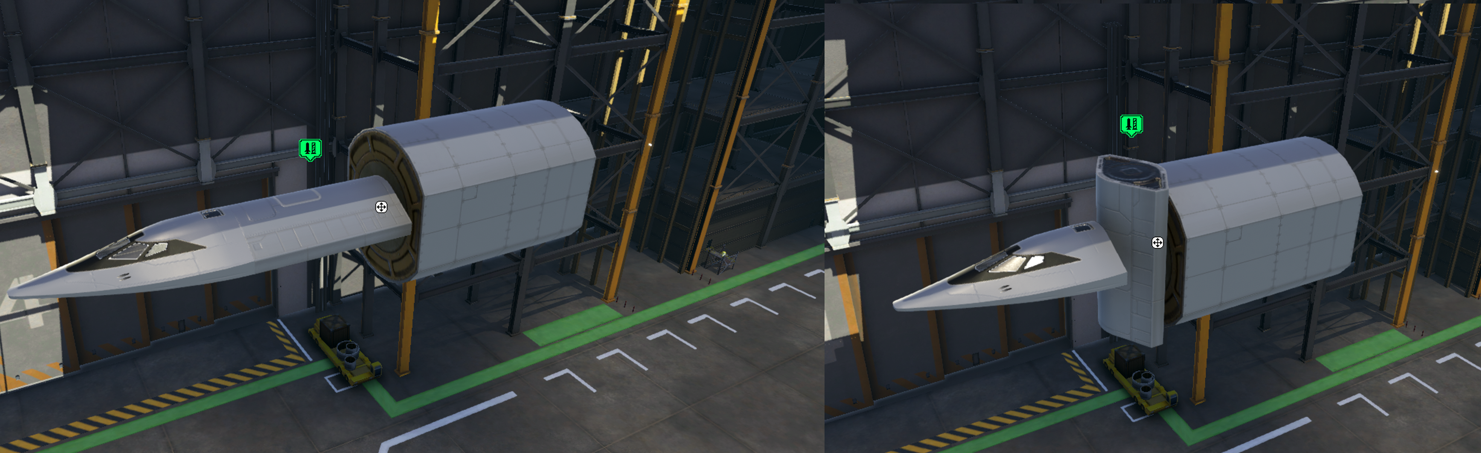 A second example of what we'd see (left) versus what the occlusion model would see (right). In this case you actually don't get much drag, because that Mk2 tank is occluding the Mk3 tank too much.
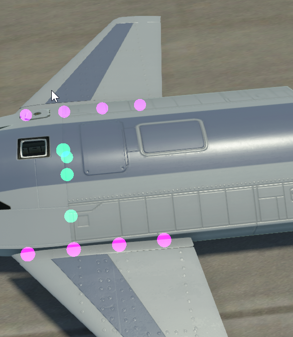
 Another Coriolis masterpiece.